550 Results
View results:
Sort by:
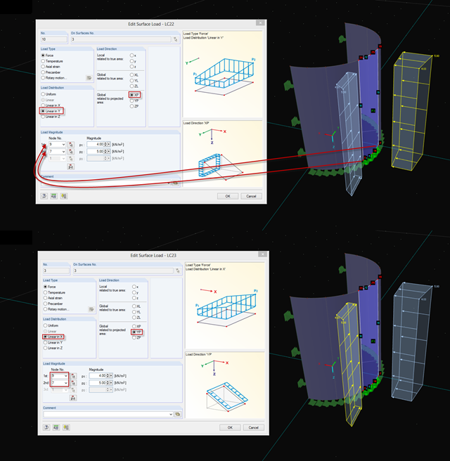
If you want to apply, for example, wind loads to a circular cylinder as defined in EN 1991‑4, Clause 7.9, proceed as follows.
If you want to simulate, for example, the failure of particular structural members, you can use the "Modify stiffness" function.

In RFEM, you have the option to create and analyze cables using sheaves. For this, use the "Cable on Pulleys" member type. It is ideal for pulley systems, where the longitudinal forces are transferred via sheaves.
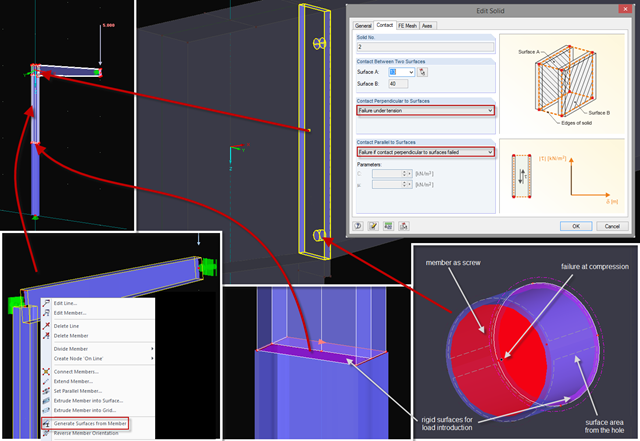
Sometimes, a detailed examination is needed of problematic areas of a joint or the stiffness of a frame joint. The following tips can help you with this. As an example, a frame joint was modeled using RF‑FRAME‑JOINT Pro and members, and used as a basis.
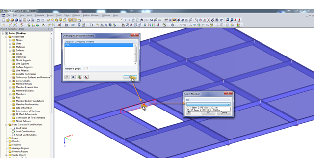
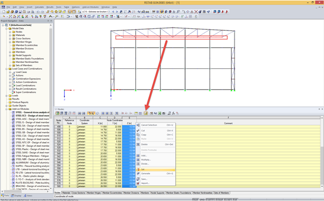
A modell check allows you to find overlapping members, among other things. However, this targeted selection could cause some minor problems. Therefore, there is a selection window now available, which appears when you click on one of the elements. This appears by clicking on one of the elements. Additional information helps you to select the correct member.
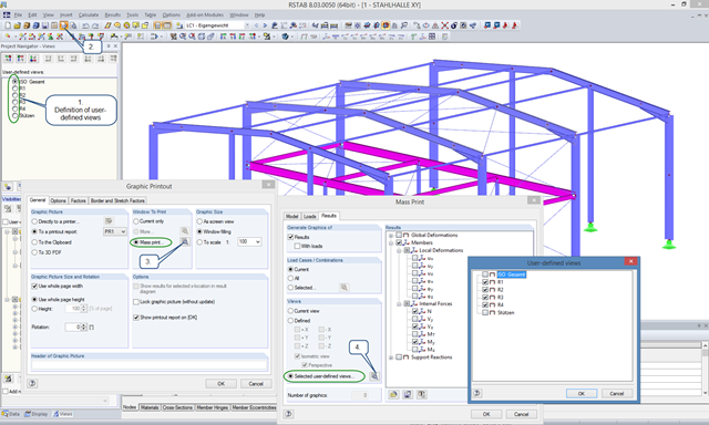
User-defined views are a very useful tool for effective modeling, as the previously selected and adapted objects appear directly with a click of the mouse. These objects can also be used easily to create informative and clearly arranged result graphics. With just a few clicks, you can create all result graphics at once using the mass print function.
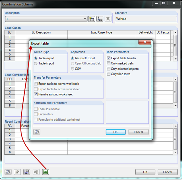
In RFEM and RSTAB, you can create a combination scheme in the combinatorics of load cases and combinations. This scheme can be used for other projects by transferring it to other computers using the Export/Import function. Thus, multiple people working on a project can use the same scheme.
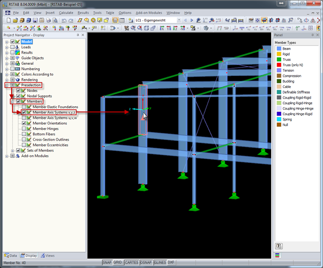
The local coordinate system of a member is particularly important when defining member end releases and member nonlinearities. The definitions follow the orientation of the axes. You can temporarily adjust the visibility of these member axes by means of preselection.
When defining real support conditions, it is always necessary to combine linear and nonlinear support conditions. This way, a beam resting on a wall can transfer compression forces to the wall and the line support (wall) will not take over the lifting forces. These forces should be carried by screws, for example, which are defined as a linear nodal support.
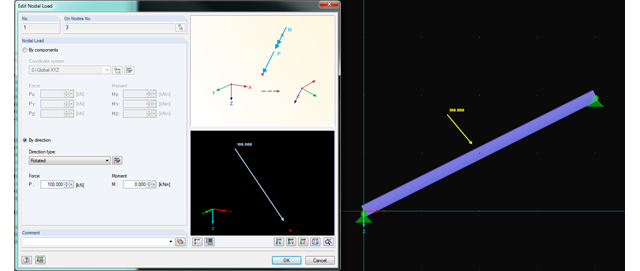
In RFEM and RSTAB, you can now rotate nodal loads or apply them on member axes. Thus, inclined members can also be loaded with nodal loads perpendicularly or along the member axis.
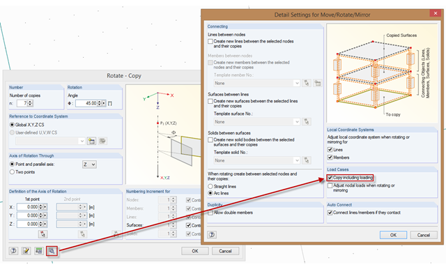
In order to also consider loading when copying, mirroring, or rotating, the corresponding option must be activated. To do this, select the corresponding check box in the "Detail Settings for Move/Rotate/Mirror" dialog box. Then, loading is included when copying until you deactivate this function.
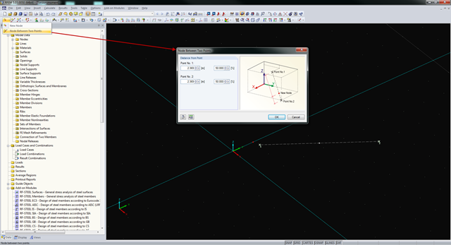
In RFEM and RSTAB, you can create nodes not only by means of coordinates, but also by means of existing nodes. You can use the "Node Between Two Points" function to create a node located on an imaginary line connecting two nodes. You can enter the distance as a percentage or according to the relative lengths.
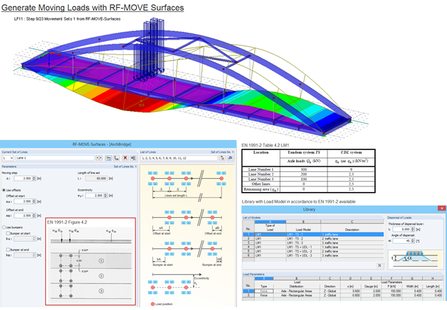
Moving loads can be generated easily with RF‑MOVE Surfaces. A library is available with load models as defined in Eurocode 1, Part 2. The input of step size, offsets at start and end, and the distance to a reference line make it possible for the user to generate user‑defined load models and influence the number of load cases generated. RF‑MOVE Surfaces generates load cases and, optionally, a result combination as an envelope of all results.
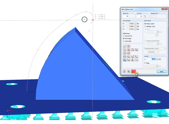
In RFEM, if you want to display a curved geometry (preferably in one continuous line), you can use splines or NURBS, for example. When modeling, you should pick the individual nodes one after another. If a mistake is made, you can go back using the special Undo function in the "New Spline Line" window. Thus, it is not necessary to enter the entire continuous line again.
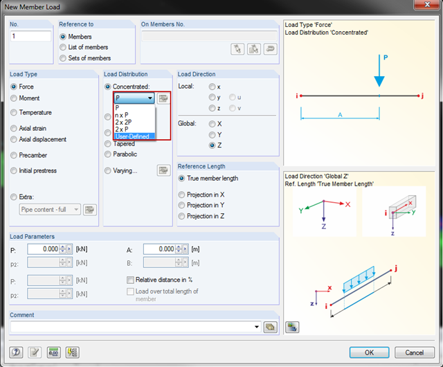
You can now also create concentrated member and line loads in RFEM and RSTAB. This is an extension of the original member/line load function. From now on, you can create several concentrated loads with uniform or user-defined load distribution on a member or a line.
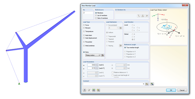
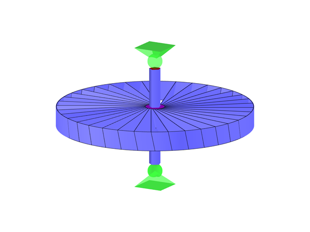
With RSTAB version 8.04.0058 and later versions, you can consider loads due to rotary motion. This load type is especially useful for crane designs (see the simplified crane in the image).
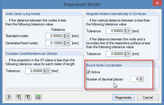
During the cooperation between the structural and design engineers, the DXF format is often used if there is no direct interface. However, the geometrical data of these DXF files are not always accurate. For example, an inaccuracy in the third decimal place is not noticeable, but it can lead to numerical problems when generating the FE mesh in RFEM.
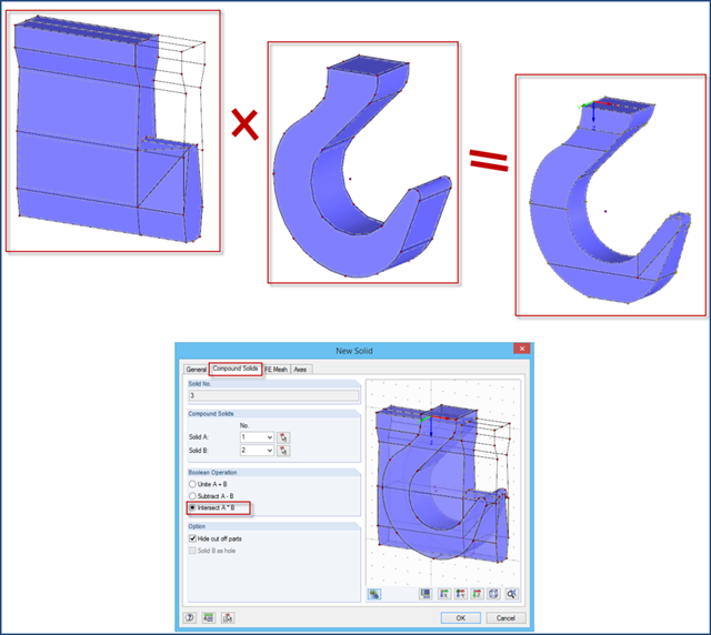
The "Intersect" option may facilitate the modeling of complex solids. This option is available in the shortcut menu after selecting two solids.
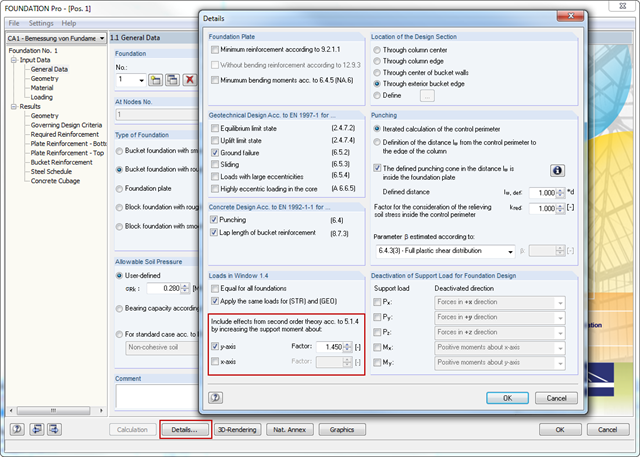
In RFEM and RSTAB, the internal forces of individual load combinations are determined according to the second-order analysis by default. If you use the RF‑CONCRETE add‑on module for stability analysis of reinforced concrete columns, you can change the calculation method of LCs to the linear static analysis, since the effects of the second‑order analysis are already considered in the calculation according to the model column method in RF‑CONCRETE Columns (nominal curvature method).
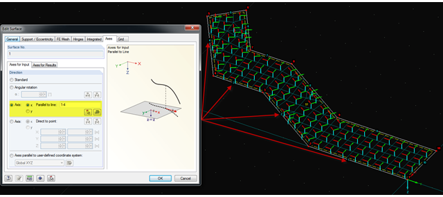
It is often necessary to adjust the FE mesh of surface elements to the geometric structure. RFEM provides various options for this. For example, the FE axis can be rotated around a point, aligned in the direction of a point, or oriented to a user-defined coordinate system. Another option is the direction parallel to a line, and in this case in particular, it is possible to enter or select several lines.
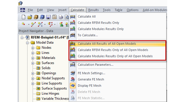
In RFEM and RSTAB, files can be computed automatically in a sequence of calculation, so the models can be processed overnight, for example.
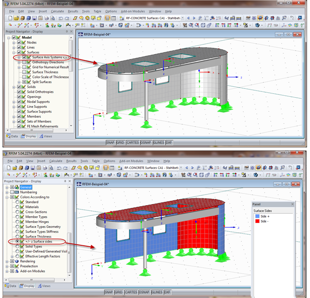
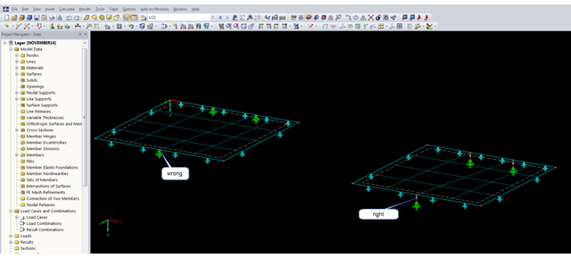
When calculating the surface reinforcement in RF-CONCRETE Surfaces, the result values for both surface sides +/- z are available. If you are unsure which side of a surface is the positive or the negative z side, you can hide the local coordinate system of each surface in the RFEM Project Navigator - Display under "Model" → "Surfaces" → "Surface Axis Systems x,y,z". In the case of complex structures, this can quickly become confusing. Displaying multiple axis systems makes it difficult to recognize the incorrect direction of a surface, for example (see the figure on the top).
In addition to the standard functions, the input tables of the main program have block functions. With these functions, you can edit the data in the selected rows and columns of the table in one step.
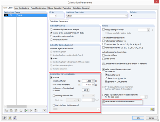
With RFEM 5.04, there are new options for the system analysis (critical load factors) of load cases and load combinations in the calculation parameters of the RF‑STABILITY add‑on module: ~ The load increment is not closed due to stability problems, but optionally also due to predetermined deformation limits. ~ The calculation method is applicable to all nonlinear calculations. ~ You can define an initial load (LC/CO) that is not increased (for example, self-weight). ~ The "Refinement of the last load increment" option provides an efficient option to determine the critical load factor as precisely as possible.
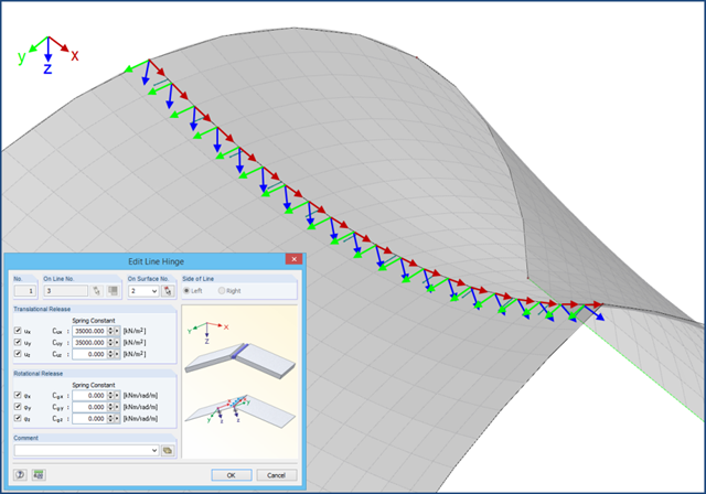
If it is impossible to transfer all internal forces from one surface to the next, you have to arrange a line hinge. To do this, use the "Edit Surface" dialog box, "Hinges" tab.
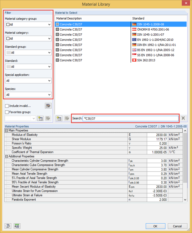
Dlubal Software Programs provide a materials library. This library covers almost all materials commonly used in civil engineering, including the corresponding parameters for calculation and design.
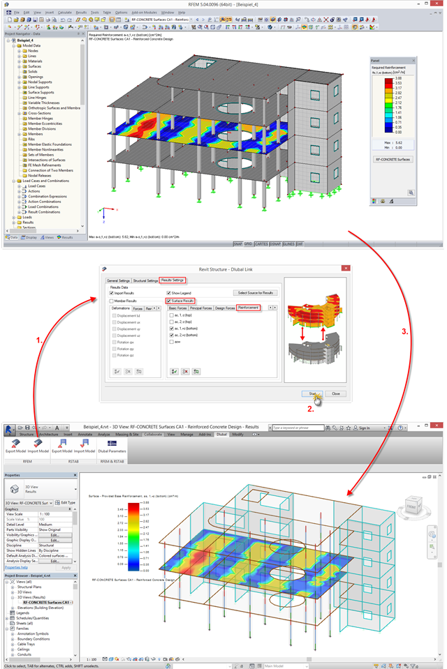
The interface between RFEM/RSTAB and Autodesk Revit has been improved: You can now transfer results from RFEM/RSTAB to Revit and display them there graphically. This option is available in a new tab when importing a file.
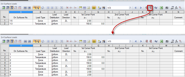
The load tables provide a simple option to control the applied loads. Dividing loads into individual lines is expedient. After dividing loads into the load table, the load data are displayed by a structural element (nodes, members, lines, surfaces, or solids). Thus, the load data analysis of each structural element is facilitated. The load case data can be compressed later.
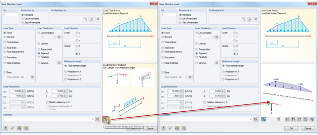
In addition to the load direction and reference length of member loads, it is now possible to display a preview of the loading.
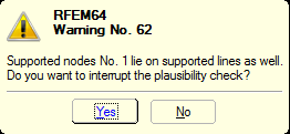
You can define nonlinear supports in RFEM and RSTAB. In RFEM, these are represented by nodal, line, and surface supports. Many customers contact us because of nonlinearities that are apparently not acting as desired. For example, there is a failing line support in a model. Since the structure is statically determined as supported, a linear nodal support is usually added. If the nodal support rests at the start or the end of a nonlinearly supported line, there is no clear definition of the degrees of freedom, so the nonlinearity cannot be considered properly. In this case, RFEM displays a warning message.